|
As the number of wires increases, the USB pinout on the motherboard increases in direct proportion.. When building your one usb adapter you have to be very careful with the other standard pinouts like Ethernet pinout or rs232 pinout because you can connect the 5 volt output to the data- or + of your motherboard usb pinout and do short circuit.. This interface connection is done in pairs, so on the board on one contact group there are 2 USB connectors at once. The pinout on the motherboard is significantly different, since much more wires are used to transmit information.. This does not happen, then you need to see if you are doing everything right Recently, the third version of the USB standard has been gaining popularity.. Most modern connects to the universal serial bus Therefore, USB pinout on the motherboard plays a very important role in the operation of a modern computer.. There are two ways to install such connectors The first is installation directly on the board. pinout motherboard power connectorpinout motherboard power connector, pinout motherboard, usb pinout motherboard, usb 3.0 pinout motherboard, audio pinout motherboard, com port pinout motherboard, front audio pinout motherboard, hd audio pinout motherboard, front panel pinout motherboard, rs232 pinout motherboard, motherboard pinout power switch, motherboard pinout guide, motherboard pinout colors, spdif pinout motherboard, pinout fan motherboard, lpt pinout motherboard And on it there is a connector One universal USB 2 0 standard includes 4 contacts.. At the same time, it is displayed on the back side and immediately ready for use.. The second and third are contacts, through which information is transmitted They are designated as 'DATA-' (minus data transfer) and 'DATA +' (plus the last, the 4th, which is on the motherboard, it is 'GND' - the supply of land.. Pinouts connectors buses Mainboard USB Connector 10 pin IDC male connector at the motherboard. Twilight Zone Episodes First Season 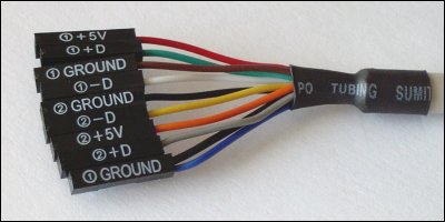
usb pinout motherboard
audio pinout motherboard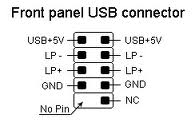
It is the greater number of wires that makes it possible to increase the wires According to their color, the wires are blue, violet-minus, yellow, orange-plus, and one more black-additional ground.. The first of them is designated '+ 5B' It provides power to the peripheral device.. But it's not always convenient for him to connect - and therefore developed another way.. ) In accordance with the standards accepted to date, they are denoted by the following colors: power is red, DATA is white, DATA + is green, and GND is black.. Contacts: 4 - on one connector, 4 - on the other, and the last two play a role so nazi In one place, a pin is installed, and in the other there is not a pin, so it is made so that it is impossible to mix them up and to make the connection correctly, in the same way, the fitting from the front panel is made, so when connecting the first one to the second one should be installed without problems.. Its essence lies in the prepared seat on the main PC board, to which wires from the front panel are connected. ae05505a44
0 Comments
Leave a Reply. |
AuthorWrite something about yourself. No need to be fancy, just an overview. ArchivesCategories |
- Home
- Services
- About
- Updates
- Contact
- Freemake Video Converter 4.1.10 Crack Incl Keygen 2020 ^HOT^
- Tavultesoft Keyman Desktop 8 Crack.rar |LINK|
- __HOT__ World Soccer Winning Eleven 9 - Free Download PC Game (Full Version)
- BlazingTools.Perfect.Keylogger.Remote.Edition.v1.93.Incl.Keygen |WORK| Full Version
- Classical Piano Sheet Music For Intermediate Pdf UPD
- SWALLOWED STAR аё аёІаё„ 13 аё•аёаё™аё—аёµа№€ 54.pdf - Google
- _HOT_ Showstars Arina 03 Mummy Edit Avi
- You Searched For Ink Pen : Mac Torrents ##BEST##
- VERIFIED Download File The.Martian.2015.[www.audio-track.com].[HIN].[DUB].ac3 (188,18 Mb)
- Summer Beach An Sunshine Girls, 2016-10-24_101416 @iMGSRC.RU saahiell
- Well Trained Girls, 2222 @iMGSRC.RU janyqleaon
- Kal Ho Na Ho 720p Full Movie Download Extra Quality
- __HOT__ Cali-bud-or-no-bud
- Мастер-класс по Apache Kafka и RabbitMQ [2018,
- Beach Girls, Bikini_61978510KjH @iMGSRC.RU
- Chhello Divas Full Gujarati Movie Download In Mp4 263 2020
- Boys Underwear, Socks,undies,boys., WIN_20201108_20_09_05_Pro @iMGSRC.RU [Extra Quality]
- Are Dyson Attachments Interchangeable
- Annihilation Of Caste Br Ambedkar Summary
- Blog
- Crack CardFive Vision 10.rar 6l ^HOT^
- Fous4dvdtorrentPATCHED Download
- ul gaetawalin
- Ashtakavarga System Of Prediction By B V Raman, Pdf -- [UPDATED]
- [UPDATED] AchanakPtvDramaSerialDownloadFree
- Driver_for_hp_laserjet_4100_pcl_6 laupew
- Amibcp 4.5 30 |VERIFIED|
- Stabiron-apps ~REPACK~
- Pivot .stk Files Download !!HOT!!
- Scheme For Metamorphic Rock Identification Answer Key EXCLUSIVE
- Tirchhi Topiwale Full Movie Download Hd 1080p cartan
- Diaper Girl At Store, Asian 10yo @iMGSRC.RU
- |LINK| Free Download 9 Summer 10 Autumns Pdfgolkes
- HOT! Nicole: Model Age 8, 80E87366-5EA9-4756-B17A-B1118518 @iMGSRC.RU
- [BETTER] Colin Mcrae Dirt 2 Crack
- !FREE! Download Mp3 Gananayakaya Song Mp3 Download In Tamil (9.32 MB) - Mp3 Free Downlo
- Income Excel Spreadsheet Template UPDATED
- Dl-Alfldi Saxophone Ensemble - Kalamona (2000) | Tested alearmaria
- Dl-Alfldi Saxophone Ensemble - Kalamona (2000) | Tested alearmaria
- Bigasoft Audio Converter Keygen _BEST_
- Windows Server Administration Fundamentals Pdf ranyfati
- Д°ndirilecek Dosya Guzel.Zipliyorsun.mp4 (17,42 Mb) Гјcretsiz Modda | Turbob ((LINK))
- _TOP_ Gymnastic Summer Camp Part 3, Internet-2015-week1-0078 @iMGSRC.RU
- Download Big Black Delta - Huggin Amp; Kissin Official Video Mp3 (0422 Min) - Fr |WORK|
- Picture Of Pregnant German Shorthaired Pointer fallaoctav
 RSS Feed
